





COMPACT CONNECTIONS · ENGINEERING SELECTION
A miniature quick disconnect can solve a packaging problem and create a flow restriction at the same time. For an equipment designer, the useful question is how to fit a serviceable connection into the available space while delivering the coolant flow the assembly needs. Start with these three requirements together rather than choosing the smallest body first.
MH designs and manufactures liquid cooling quick disconnects with an aerospace fluid-control background and experience serving high-reliability cooling applications, including data centers, AI servers, supercomputers and equipment cooling. Small connection designs are a particular strength. This article explains how to turn a compact-connection requirement into a useful engineering enquiry.
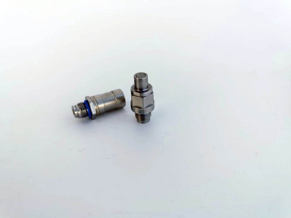
A compact blind-mate connection example from the MH liquid cooling catalog. The connection structure, mounting arrangement and mating space need to be considered together.
1. Define the Space the Complete Connection Needs
A product body diameter is only one part of the installation envelope. Check the assembled mating pair, end connections, adjacent components and the path used to install or remove the cooled assembly. A compact body may still need additional room for hose routing, a locking sleeve or module withdrawal.
For a manually operated connection, leave access for the intended grip and release action. For a blind-mate connection, define the insertion direction, equipment guidance, alignment tolerances and the way the assembly is retained after mating. A floating interface can help accommodate misalignment, but its permitted movement must come from the specific design.
Provide an installation sketch with the available length, width and height. Mark fixed interfaces, keep-out zones and the service direction. These details are often more useful for the first discussion than a request for the smallest available coupling.
2. Keep Passage Size Separate from Outside Dimensions
The MH catalog includes a 6xx-QD example with a 2.5 mm passage. This is an internal flow dimension, not the body outside diameter. The drawing also shows individual half lengths of 24.20 mm and 25.50 mm and a reference connected length of (43.40) mm. The connected length does not include every clearance required to install and service an assembly.
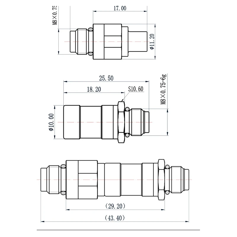
Use the dimensioned mating-pair drawing to review the interface. Passage, body envelope and service clearance describe different requirements.
The catalog also contains other passage sizes and connection structures. These examples demonstrate available design approaches; they do not define the limits of MH custom development. A small-bore starting point should be retained only if it also meets the required flow and installation conditions.
3. Compare Flow at an Agreed Pressure Drop
Specify the flow required through the connection and the pressure-drop budget available for the complete connected pair. Working pressure describes the pressure the assembly must withstand; it does not tell you how much pressure is lost as coolant flows through it.
For each operating condition, compare the same coolant, temperature, flow rate and mating configuration. Record where pressure is measured and whether the result includes the end connections. A valve opening, internal transition or termination can influence the result even when two products have the same nominal passage size.
In a series flow path, the losses through the supply and return connections, tubing, cold plate and other components contribute to the loop requirement. In a system with parallel branches, check the relevant branch flow and pressure balance rather than adding every branch connection into one series path.
MH can work with your target flow and allowable pressure drop to define the connection and verification requirements. A passage dimension by itself is insufficient to assign a flow rating. Ask for performance evidence for the proposed mating pair and agreed operating conditions.
4. Make the Selection Trade-Off Explicit
| Selection item | Information to provide | Why it matters |
| Installation envelope | Connected length, body size, end geometry and removal path | Fits the equipment and remains serviceable. |
| Flow requirement | Required flow per branch and operating range | Supports the cooling requirement at the connection location. |
| Pressure-drop budget | Allowable loss across the specified mating pair | Can be assessed against the available pump and loop budget. |
| Coolant and temperature | Fluid formulation, concentration and temperature range | Sets the basis for seal compatibility and performance evaluation. |
| Mating method | Manual or blind-mate operation, guidance and retention | Matches the equipment assembly and maintenance method. |
| Acceptance criteria | Leakage, disconnect release, cycling and inspection requirements | Defines how the supplied configuration will be accepted. |
5. Connect the Design to Manufacturing and Verification
In a small connection, the valve arrangement, seal-contact surfaces and mating geometry must work within a limited envelope. MH combines interface and valve design with precision machining, assembly and testing, so a packaging change can be considered alongside its manufacturing and functional implications.

Machining equipment arranged on the production floor supports the manufacture of connection bodies and precision fluid-control components.
For a custom project, MH can participate in development from interface dimensions, operating conditions and performance requirements. You can bring an equipment layout or an existing mating requirement to the discussion; a fully completed production drawing is not the only starting point.
High-reliability selection also needs more than a small package. Specify connected sealing, disconnected self-sealing and fluid released during operation as separate acceptance concerns. MH reports a guarantee of no more than one drop over 100 connection/disconnection cycles; selected designs have also shown no observed drop over several hundred operations in tests. Confirm the relevant model, test conditions and acceptance method for your project rather than treating these statements as a universal zero-leak claim.
Questions Equipment Engineers Often Ask
Does a smaller passage always mean an unsuitable connection?
No. Suitability depends on the required flow and allowable loss as well as the installation. A small connection may be appropriate for one branch and unsuitable for another with a different cooling duty.
Can a miniature quick disconnect fitting replace an existing connector directly?
Compare the complete mating interface, end connections, mounting details, seals and operating requirements. Similar appearance or nominal size does not establish interchangeability.
What if I have the equipment layout but have not selected a model?
Send the layout, coolant details, flow target and pressure-drop budget. MH can discuss a catalog starting point or a custom interface and identify the performance checks needed for the proposed assembly.
Discuss Your Compact Cooling Connection with MH
Send a sketch or CAD view showing the available space, together with coolant, temperature, required flow and pressure conditions. If you already have a connection concept, include its mating method and the issue you need to solve: access, envelope, flow restriction or serviceability.
For connection examples, see MH blind-mate liquid cooling quick disconnects. If your interface needs development, explore custom liquid cooling quick disconnects.