





PRESSURE RATINGS · CONNECTION AND SERVICE
When selecting a connect under pressure coupling for liquid cooling, first define the pressure conditions during mating and separation. Your cooling loop operates within a coupling's working-pressure rating. Does that mean a technician can reconnect the same coupling while the line remains pressurized? That question needs a separate answer. The pressure a connected assembly can contain and the pressure at which its valves and locking mechanism can be operated describe different duties.
For equipment manufacturers, the distinction affects connector selection, module replacement and maintenance instructions. MH combines aerospace fluid-control experience with the design and manufacture of compact liquid cooling quick disconnects, serving high-reliability equipment, data center, AI server and supercomputer cooling applications. A useful specification describes the pressure conditions at each stage of use.

MH threaded-lock liquid cooling connection examples. Specify pressure capability for the complete mating pair and its intended operating sequence.
Working Pressure and Connection Pressure Answer Different Questions
| Parameter | What it describes | What to specify |
| Working pressure | The specified pressure for the connected assembly during operation. | Check the selected configuration, coolant and temperature conditions. |
| Pressure during connection | Pressure present while the two halves are being brought together and the valves open. | State pressure in each half and the required connection force or torque. |
| Pressure during disconnection | Pressure present while the locking interface releases and the halves separate. | Confirm the permitted operation and applicable release or retention requirements. |
| Residual pressure | Pressure remaining in a line or isolated section before reconnection. | Describe where it is trapped and how it will be managed. |
| Pressure drop | Pressure lost as coolant flows through the connected pair. | Use it for flow and pump-budget assessment; it is a separate parameter. |
A Catalog Example: 3 MPa Working, 1 MPa Connection and Disconnection
The MH liquid cooling catalog lists ZFJ1-3003.00 with a 3 mm passage and ZFJ1-3006.01 with a 6 mm passage. For both examples, the stated working pressure is 3 MPa and the stated connection/disconnection pressure is 1 MPa. These are separate ratings on the same catalog entry.
For a requirement involving connection or disconnection at 2 MPa, the 3 MPa working-pressure value is therefore insufficient evidence of suitability. The catalog connection/disconnection figure must be considered, and a configuration meeting the actual service requirement must be selected or developed.
The figures above belong to these two catalog examples. They should not be applied to every MH coupling, another mating combination or a custom interface. When requesting a quotation, keep the working-pressure requirement and the connection/disconnection requirement on separate lines.
Selecting a Connect Under Pressure Coupling: Define Both Sides
A single statement such as "connect at 1 MPa" can leave important questions unanswered. Is one half pressurized while the other is at a lower pressure? Are both halves pressurized? Are the pressures equal? Provide the pressure in each half immediately before mating and identify whether the equipment is isolated or coolant is flowing.
Pressure acts on the internal valve arrangement during engagement. Connection effort depends on the design as well as pressure, seal friction and spring loading. For a manual coupling, establish an acceptable operating force or torque. For a blind-mate assembly, account for the combined connection load in the equipment guidance, drive and retention design.
A threaded locking mechanism can provide a controlled way to engage a mating pair, but the presence of threads alone does not establish a particular connect-under-pressure capability. Likewise, a thread on a hose or equipment port is a termination detail, rather than proof of how the mating interface locks.
Account for Residual Pressure During Module Replacement
Consider a removable cooling module after its isolation valves have been closed. Stopping the pump does not, by itself, establish zero pressure in every isolated section. The relevant service condition is the pressure actually present at the two coupling halves before the next connection.
Define the intended sequence: isolate the branch, manage pressure as required by the equipment procedure, disconnect, replace the module and reconnect. If the project requires operation with residual pressure, include that requirement at the design stage. Do not assume that an unspecified pressure-relief function is present in the selected connector.
Operation under pressure also differs from operation under flow. A connection/disconnection pressure figure alone does not establish suitability for disconnecting a flowing coolant stream. State whether flow is stopped and identify any transient-pressure requirements for the proposed sequence.
Turn the Service Condition into a Testable Requirement
A useful acceptance plan states the mating-pair configuration, coolant, temperature, pressure in each half and operation sequence. It also defines the allowed force or torque, connected sealing, disconnected self-sealing and fluid released during the operation. Those checks answer different questions and should be recorded separately.
For repeated operation, define the number of cycles and the conditions at which they are performed. A static pressure-hold result cannot establish operation force or fluid release over repeated connection cycles. Similarly, a low-spillage result does not establish the pressure at which the coupling may be operated.
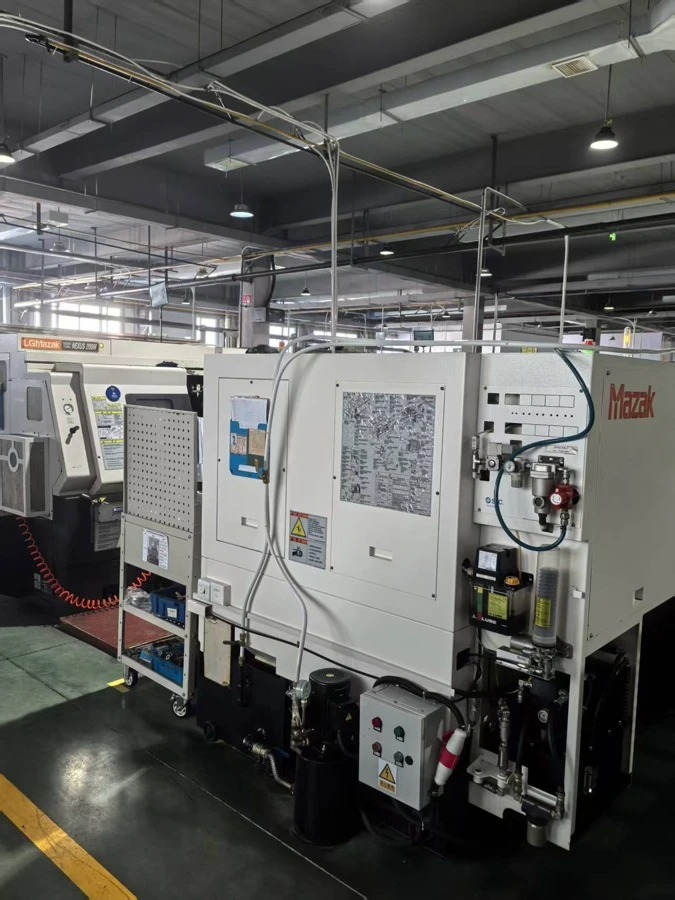
Precision machining on the production floor supports connection bodies, valve components and mating features. Their geometry must be considered together with sealing, assembly and the specified pressure duty.
MH supports in-house engineering and manufacturing for liquid cooling connections, including precision machining, valve design, assembly and testing. Customers can provide their interface, operating conditions and performance targets for OEM/ODM development. This allows the connection requirement to be discussed as a working fluid-control assembly, alongside its installation and manufacturing needs.
What to Include in Your Enquiry
Send the normal and maximum working pressures, coolant and temperature range, plus the pressure in each half before connection and disconnection. Add the required flow, whether operation occurs under flow, the mating method and any force or torque limit. An interface drawing and a short description of the replacement sequence help connect the pressure requirements to the equipment design.
If you have an existing connector, include the complete mating-pair identification and the specific issue: difficult reconnection, trapped pressure, excessive operating effort or a new service-pressure requirement. MH can discuss an existing design or a custom connection approach against those conditions.
Explore MH liquid cooling quick disconnects for connection structures, or see custom liquid cooling quick disconnect development when your interface or operating sequence needs engineering input.