





2x BLIND-MATE SERIES · 2.5 / 6 / 14 mm PASSAGES
Blind Mate Quick Disconnects for Liquid-Cooled Modules
A rear-mounted fluid connection can be difficult to reach once a cooled module is installed. A blind-mate coupling engages along the module's insertion path, so the equipment can bring the two fluid halves together without a separate hand-operated sleeve at the coupling face. MH's illustrated 2x designs use double shut-off valves and work with equipment-side guidance and retention. With aerospace fluid-control experience and actual high-reliability cooling applications, MH supports both existing connection designs and equipment-specific interfaces.
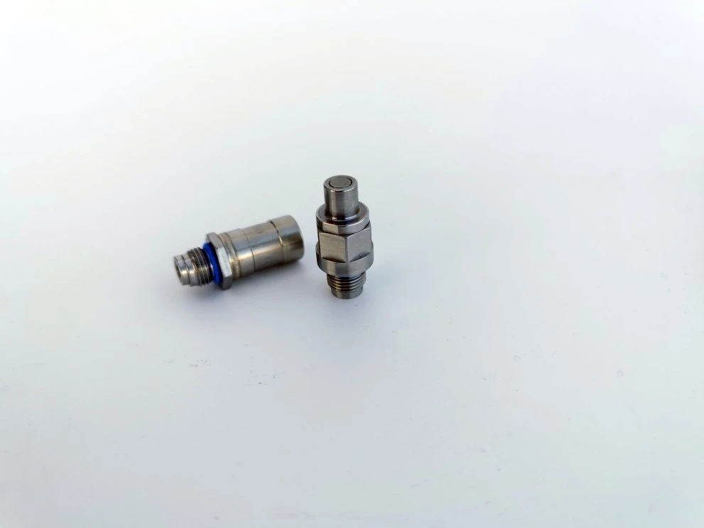
The 2.5 mm passage example above is the smallest-bore design shown on this page. Use the dimensional views below to assess its actual installation space.
Which of These Three Designs Is the Best Starting Point?
Begin with the space and mating arrangement, then check the individual pressure, temperature and fluid requirements. The three catalog examples represent different interfaces; they are not a single connector offered with interchangeable bore inserts.
| Design to review | First selection question |
| 6xx-QD · 2.5 mm | Does the small-bore pair fit the available module envelope and line route? Check both separated halves and the connected view. |
| ZFJ3-2106.00 · 6 mm | Does the 6 mm passage suit the circuit, and can both ends be mounted in the shown orientation? Review required flow and pressure loss separately. |
| ZFJ1-2014.00 · 14 mm | Can the equipment accommodate the larger pair and its threaded end geometry? Check the connected length and adjacent hardware. |
Model Drawings and Individual Operating Ratings
Each specification below belongs to its named design. A passage diameter is the internal bore, not the outside diameter, installation envelope or a guaranteed flow rate.
6xx-QD - 2.5 mm Passage
| Passage | 2.5 mm |
| Working pressure | 1.5 MPa |
| Operating temperature | −55 to +130°C |
| Listed media | Coolant, PAO and specified refrigerant |
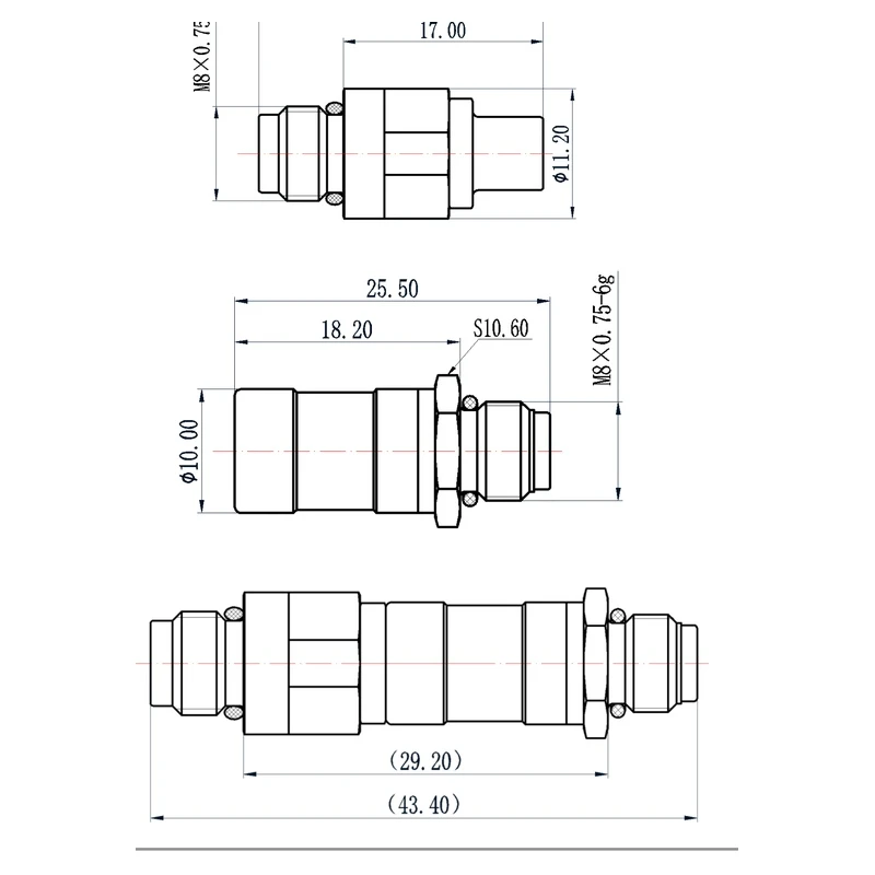
The small-bore 6xx-QD example is useful when discussing a compact fluid interface within a constrained module layout. Review both ends and the connected geometry in the drawing, together with the space needed for insertion and mounting.
ZFJ3-2106.00 - 6 mm Passage

| Passage | 6 mm |
| Working pressure | 1.6 MPa |
| Operating temperature | −55 to +135°C |
| Listed media | 65# coolant, PAO and specified refrigerant |

The ZFJ3-2106.00 drawing shows the two mating halves and the connected arrangement. End-interface geometry, line termination and installation orientation should be reviewed as a complete pair.
ZFJ1-2014.00 - 14 mm Passage

| Passage | 14 mm |
| Working pressure | 0.85 MPa |
| Operating temperature | −60 to +175°C |
| Listed media | 65# coolant, PAO and specified refrigerant |

ZFJ1-2014.00 illustrates a larger interface within the same blind-mate product family. Its drawing includes end-thread and connected-length information for checking the installation envelope. The different passage size does not establish a flow or pressure-drop rating.
What the Mating Views Tell the Equipment Designer
Read each drawing as a pair. The individual half views help locate the ports and mounting features; the connected view shows the assembled relationship. A line-end dimension alone cannot establish whether the full module will seat correctly.
| Drawing check | Equipment decision |
| Mounting reference | Locate each half from the equipment's mounting datums. Include bracket position and port orientation, rather than checking only the connector centerline. |
| Connected position | Confirm where the fluid halves sit when the equipment reaches its seated position. Account for the connector pair and nearby fittings in the same envelope. |
| Insertion direction | Show the travel direction and available approach space. A compact final assembly still needs a workable path into engagement. |
| Line routing | Check whether tubes, hoses and adapters obstruct the travel path or service access. Include the termination hardware, not only the coupling body. |
Guided Engagement: Three Different Mechanical Jobs
The module guide, floating connector mount and retaining structure have different functions. Defining all three avoids asking a fluid interface to perform the job of the equipment mechanism.
1. Guide the module before the fluid halves engage
Guide pins or an equivalent guiding arrangement establish the approach of the two halves. The guide system should control the equipment motion; the coupling should not become the locator that pulls a misaligned module into position.
2. Provide the required radial accommodation
The 2x series incorporates radial float. Its purpose is to accommodate the alignment relationship during guided mating. Define the required offset allowance against the equipment mounting tolerance stack. Guidance controls the insertion path; radial float accommodates the alignment relationship within the selected design's allowance.
3. Retain the seated module independently
These illustrated couplings have no internal locking mechanism. An equipment-side retaining arrangement must hold the connected position. Identify that arrangement on the assembly sketch, together with the seated position, rather than assuming that valve engagement locks the module.
Double Shut-Off During Module Removal
When the mating halves separate, the valves close on both sides. This provides shut-off at the two disconnected fluid ends. It does not specify the pressure at which the equipment may be inserted or withdrawn: the listed working-pressure rating describes a different operating condition.
For a removable cooling assembly, define the service sequence as well as the operating duty. If residual pressure may remain when the module is moved, include that condition in the interface review. Also distinguish liquid released at disconnection from external leakage while the pair remains coupled.
Where a Blind-Mate Arrangement Is Useful
| Equipment layout | Reason to evaluate this structure |
| Slide-in cooled electronic module | Fluid engagement can follow the same direction as module installation, when guides and external retention are incorporated into the equipment. |
| Removable assembly with rear fluid ports | The coupling face may be inaccessible for manual sleeve operation after installation. Check the approach path and the complete mating pair. |
| Dense equipment with several interfaces | Fluid port positions must be coordinated with other mechanical or electrical connections. Review the collective alignment and insertion sequence. |
MH's wider liquid-cooling experience includes data centers, AI servers, supercomputers and high-reliability equipment. These equipment layouts are useful starting points for selecting the mating pair and defining the installation requirements.
Pre-Selection Notes for the Cooling Circuit
Fluid: the catalog lists coolant, PAO and refrigerant categories, with 65# coolant named for two examples. Identify the actual formulation and additives when selecting seals and wetted materials. A generic refrigerant description is not a compatibility approval for every refrigerant.
Hydraulic duty: provide the required flow and acceptable pressure loss. The 2.5, 6 and 14 mm bores alone do not establish flow capacity or pressure-drop performance.
Temperature: use the range of the selected model. Use the pressure and temperature ratings together for the named model.
Clean interfaces: keep mating faces protected during installation and service, and use the specified clean, filtered fluid. Blind access makes planning for inspection and contamination control particularly useful.
Manufacturing That Connects the Interface with Reliable Function
A blind-mate cooling connector must open, seal and engage as a complete assembly. MH combines valve and seal engineering with precision machining, assembly and testing. Mating geometry, mounting features and sealing fits are carried from the interface definition into manufacture.
Precision manufacturing on the production floor. CNC resources support the geometry and functional features of fluid-control components.
Fluid-control components in the assembly workspace. Component manufacture and assembly requirements are linked to the finished connection function.
MH's stated liquid cooling connection sealing guarantee is no more than one drop over 100 connection/disconnection cycles. The cycle figure is not a product service-life limit. Selected models have also completed several hundred mating operations without an observed drop in testing; those results belong to the products tested. Define the verification conditions for the proposed connection.
Choose the Next Step for Your Equipment
Need to compare operation methods? See manual liquid cooling quick disconnects. For supplier background and manufacturing strengths, read MH's liquid cooling connection capabilities. Return to the liquid cooling quick disconnect range for other structures.
Send a Module Layout for a Focused Interface Review
A useful first sketch shows the two mounting faces, insertion arrow, seated position, guide arrangement and external retention. Add the preferred model or bore, coolant and main operating conditions where known. The discussion can start before the assembly drawing is complete.
Review a Blind-Mate Installation
If the existing examples do not fit your interface, see Custom Liquid Cooling Quick Disconnects for MH's OEM/ODM development scope, manufacturing approach and sealing experience.
Hot Tags: blind mate quick disconnect; liquid cooling quick disconnects; blind mate cooling connectors, compact blind mate liquid cooling quick disconnects; blind mate cooling connectors; module cooling connections, Blind Mate Quick Disconnects, China Blind Mate Quick Disconnects manufacturers, suppliers, factory


