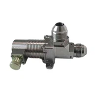





10 / 90 SERIES · MANUAL CONNECTIONS FOR HIGH-RELIABILITY COOLING
Manual Liquid Cooling Quick Disconnects for Accessible Service Connections
MH designs and manufactures manual liquid cooling quick disconnects for accessible cooling lines, cold-plate connections and removable equipment assemblies. Pin-locking and ball-locking designs combine mechanical retention with shut-off valves. Compact interfaces are a particular strength, supported by an aerospace fluid-control background and practical experience in AI server, supercomputer and other high-reliability cooling applications. Send your connection layout to discuss an existing design or an OEM/ODM adaptation.

ZFJ2-1006.00N/S: a 6 mm pin-locking example for compact equipment cooling connections.

ZFJ1-9010.00: a 10 mm ball-locking example. Compare its mating and end geometry with the drawing below.
Machining the Mating and Valve Features

Precision machining produces the coupling bodies, valve parts and end features that establish the fit of the complete connection.
For a compact manual connection, the locking parts, valve movement and sealing surfaces must work within the available space. MH connects interface design with precision manufacture, assembly and functional verification, so a change to a port or mounting feature is considered together with the operation of the complete pair.
Manual Locking Connections for Accessible Cooling Lines
MH supplies pin-locking and ball-locking liquid cooling quick disconnects for connections that an operator can reach during equipment assembly or service. These push-pull structures combine mechanical retention with shut-off valves, allowing the fluid line to be separated without relying on a module chassis to hold the coupling together.
Small-bore cooling connections are a particular MH strength. The examples here include 6 mm passages alongside 8, 10, 12 and 16 mm designs. Each model has its own working-pressure and temperature ratings; choose the complete mating pair for the equipment.
Choose the Locking Structure Around the Service Operation
| 10 series: pin-locking | 90 series: ball-locking |
| The catalog describes locking segments operated by a push-pull action. Review the body, operating access and end geometry together. | Steel balls provide retention with push-pull operation. The series includes flat-face arrangements and a specific self-pressure-relief model. |
| Consider when the illustrated pin-locking interface fits the cooling line or cold-plate connection. | Consider when the illustrated ball-locking pair and release arrangement fit the service location. |
Neither structure can be selected from bore size alone. Leave room for a hand to operate the release, for the two halves to separate and for attached lines to move without forcing the coupling sideways.
Seven Designs at a Glance
| Model / structure | Passage / working pressure | Temperature / feature |
| ZFJ2-1006.00N/S · Pin | 6 mm / 10 MPa | −55 to +150°C |
| ZFJ1-1006.00 · Pin | 6 mm / 1.6 MPa | −55 to +135°C |
| ZFJ1-1016.00 · Pin | 16 mm / 0.85 MPa | −60 to +175°C |
| ZFJ1-9008.00 · Ball | 8 mm / 1.72 MPa | −60 to +175°C |
| ZFJ1-9010.00 · Ball | 10 mm / 1.72 MPa | −60 to +175°C |
| ZFJ1-9010.01 · Ball | 10 mm / 1.72 MPa | −60 to +175°C · Self-pressure-relief |
| ZFJ1-9012.01 · Ball | 12 mm / 1 MPa | −60 to +175°C |
Ratings belong to the named models. The two 6 mm designs have different ratings, and the .01 relief function is not a feature of every 10 mm connector.
Product Features That Matter in Equipment Cooling
| Feature | Value in the equipment |
| Push-pull mechanical locking | Allows hand operation at an accessible service point, with retention provided by the selected coupling structure. |
| Shut-off on separation | Closes the fluid ends when the mating halves separate; coupled sealing and disconnect release are assessed separately. |
| Flat-face designs in the 90 series | Provide accessible mating faces for cleaning and help address contamination at the connection interface. |
| Small-bore and adaptable end geometry | Supports cooling-line and cold-plate layouts where port location and operating access matter. |
10 Series - Pin-Locking Model Drawings
ZFJ2-1006.00N/S
| Passage | 6 mm |
| Working pressure | 10 MPa |
| Operating temperature | −55 to +150°C |
| Catalog media | 65# coolant, PAO and refrigerant (exact formulation to be specified) |

The 6 mm, 10 MPa example: review the N/S end configurations and complete mating geometry. Its working-pressure rating does not establish a pressure for manual disconnection.
ZFJ1-1006.00
| Passage | 6 mm |
| Working pressure | 1.6 MPa |
| Operating temperature | −55 to +135°C |
| Catalog media | 65# coolant, PAO and refrigerant (exact formulation to be specified) |

A second 6 mm pin-locking design, rated at 1.6 MPa. Compare its port and installation dimensions with the higher-pressure example rather than selecting by bore alone.
ZFJ1-1016.00
| Passage | 16 mm |
| Working pressure | 0.85 MPa |
| Operating temperature | −60 to +175°C |
| Catalog media | 65# coolant, PAO and refrigerant (exact formulation to be specified) |

The 16 mm pin-locking example provides another geometry for line integration. Check the 0.85 MPa rating and the space required for hand operation.
90 Series - Ball-Locking Model Drawings
Compare the 8 and 10 mm examples at their individual ratings, then review the 12 mm design separately. The 10 mm .00 and .01 versions are different models; the self-pressure-relief feature belongs to .01.
ZFJ1-9008.00
| Passage | 8 mm |
| Working pressure | 1.72 MPa |
| Operating temperature | −60 to +175°C |
| Catalog media | 65# coolant, PAO and refrigerant (exact formulation to be specified) |

The 8 mm ball-locking drawing shows the interface and installed dimensions for comparison with your service location.
ZFJ1-9010.00
| Passage | 10 mm |
| Working pressure | 1.72 MPa |
| Operating temperature | −60 to +175°C |
| Catalog media | 65# coolant, PAO and refrigerant (exact formulation to be specified) |

The 10 mm .00 drawing is the reference for this ball-locking pair. Keep it separate from the .01 version when requesting a quotation.
ZFJ1-9010.01
| Passage | 10 mm |
| Working pressure | 1.72 MPa |
| Operating temperature | −60 to +175°C |
| Catalog media | 65# coolant, PAO and refrigerant (exact formulation to be specified) |

The 10 mm .01 version adds the catalogued self-pressure-relief function. Discuss its role in your isolation and maintenance sequence.
Model-specific function: ZFJ1-9010.01 includes a self-pressure-relief valve. Its operating behaviour must be matched to the equipment sequence. This feature does not establish a permitted pressure for manual connection or disconnection, and is not attributed to every 90-series model.
ZFJ1-9012.01
| Passage | 12 mm |
| Working pressure | 1 MPa |
| Operating temperature | −60 to +175°C |
| Catalog media | 65# coolant, PAO and refrigerant (exact formulation to be specified) |

The 12 mm example is rated at 1 MPa. Confirm both the mating arrangement and the required fluid performance; passage diameter alone does not determine flow or pressure drop.
Check the Space Needed to Unlock and Disconnect
| Installation question | What to review |
| Can the release be reached? | Include nearby cold plates, brackets, panels and insulation in the service layout. A coupling that fits when connected may still be difficult to release. |
| Can the halves withdraw? | Check separation travel and the movement of the attached tube or hose. Allow access to protect and inspect the disconnected ends. |
| Does the line impose a side load? | Review line routing and support. Do not rely on the connection to correct a forced tube alignment. |
| Can the operator identify the pair? | Define the matching halves and line identification. Similar appearance or equal bore size does not prove interchangeability. |
Sealing and Pressure During Servicing
The catalog structures provide shut-off when separated and maintain sealing when connected. Distinguish three conditions in the equipment specification: leakage while coupled, shut-off at the disconnected ends, and liquid released during the act of separation. These are different acceptance subjects.
A working-pressure rating is not an instruction to disconnect under that pressure. Specify whether the circuit is isolated and depressurized before servicing, and identify any residual pressure that may remain. The 10 MPa rating of ZFJ2-1006.00N/S belongs to that model; it is not a general rating for the 6 mm family.
Select Media and End Connections Together
Use the exact coolant formulation, additives and operating temperature when selecting seals and wetted materials. The catalog's generic refrigerant reference does not establish compatibility with every refrigerant. PAO compatibility also does not automatically establish compatibility with any water-based coolant.
For water cooling quick disconnect or coolant quick connect requirements, send the exact coolant specification rather than only the general fluid name. The series support equipment-specific end dimensions and different connections to cooling lines or cold plates. Start with the port, line termination and installation orientation, while retaining the correct mating geometry and locking operation.
Aerospace Fluid-Control Experience for Equipment Cooling
MH combines valve and seal design, precision manufacture, assembly and testing with actual experience in data centers, AI servers, supercomputers and other high-reliability cooling applications. For a manually serviced connection, this engineering background is applied to the functional relationship between retention, shut-off action and the equipment interface.
Controlling Fit, Surface Condition and Shut-Off Performance

Precision turning resources support the manufacture of coupling bodies, valve parts and mating features.

Coordinate measurement supports inspection of specified geometry and mounting relationships.

Coolant test equipment supports functional and sealing verification to the agreed project requirements.
MH brings together valve and seal design, precision manufacture, assembly and testing. For these connections, the important outcome is that mating features, sealing interfaces and shut-off parts work together as a finished assembly.
Our stated liquid cooling connection sealing guarantee is no more than one drop over 100 connection/disconnection cycles. Selected models have also completed several hundred mating operations without an observed drop in testing. These selected-model results are not attributed to all seven catalog models; the relevant conditions and acceptance method are defined for the specified product.
Questions About Manual Cooling Connections
Does the same 6 mm passage mean the same rating?
No. The two 6 mm pin-locking examples on this page have different pressure and temperature ratings. Compare the named model and drawing.
Do all ball-locking versions relieve pressure?
No. The catalog identifies self-pressure-relief for ZFJ1-9010.01 specifically.
Can a manual coupling replace a blind-mate connection?
Review how the equipment is installed and serviced. A manual release needs operating access; an inaccessible module interface calls for a different integration approach.
What is needed to evaluate a water cooling quick disconnect?
Share the water/glycol formulation, additives, temperature range, pressure, flow and material restrictions. MH can review the seal and wetted-material selection for the specified fluid and duty.
Does the catalog passage range limit custom development?
The 6–16 mm passages on this page describe these seven examples. For a different envelope, interface or performance requirement, send a sketch for engineering review.
Send the Connection and Service Layout
Start with a photo, sketch or drawing of the port, line route and available hand access. Add coolant formulation, working and residual pressure, temperature, required flow and allowable pressure drop where known. Tell us how often the connection is serviced and how liquid release will be accepted. MH can review an existing mating pair or participate in interface and valve development before the full equipment drawing is complete.
Discuss a Manual Cooling Connection
For a new interface or a dedicated valve function, see Custom Liquid Cooling Quick Disconnects.
For a rear connection operated by module insertion, review blind-mate liquid cooling quick disconnects. For the wider range, explore MH liquid cooling quick disconnects.
Hot Tags: liquid cooling quick disconnects; coolant quick disconnect; coolant quick connect, manual liquid cooling quick disconnects, China manual liquid cooling quick disconnects manufacturers, suppliers, factory