






YKF / LIQUID-PRESSURE CONTROL / FUELING CIRCUIT INTEGRATION
Connect the Control Requirement to the Fueling Duty
MH YKF hydraulically operated refueling valves are custom components for large fueling equipment and aviation ground-support projects. They suit equipment programs where a liquid-pressure control requirement must be matched to the required fuel-flow operation, installation and sealing specification.
Our custom refueling range provides series flow capability up to 1,000 L/min (264 US GPM), mechanical automatic control without electronic devices, and aluminum-alloy or stainless-steel material options. Select the YKF configuration around the circuit duty rather than the external shape alone.

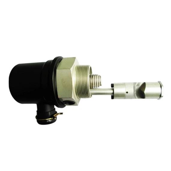
YKF example with threaded installation features and an extended body arrangement.
Define Two Sets of Conditions
For a liquid-controlled refueling valve, distinguish the conditions used to command the valve from the conditions in the fuel passage. Identify the control medium instead of assuming it is hydraulic oil. Provide the equipment circuit so the control connections and working-fluid connections can be assigned correctly.
| Control input | Control-fluid identity, available pressure range, how the command is applied and removed, and any control-line restrictions. |
| Fuel passage | Fuel type, inlet and outlet pressures, required flow and acceptable pressure drop. |
| Required response | Valve state for each command, transition requirements and the required behavior when control pressure is unavailable. |

An alternative YKF exterior. Port identification and circuit role are established by the configuration drawing.
Review the Command Sequence Before Releasing the Design
Describe the sequence from standby through fueling and shutdown. State when the control signal is present, the intended valve state, and the pressures expected during each transition. If the application requires a defined response to a broken or depressurized control line, include that requirement explicitly.
For an equipment upgrade, provide the existing circuit and identify connections that must remain compatible. For a new module, an operating sequence and installation drawing can be the starting inputs; MH can develop the internal design rather than requiring customer-supplied component drawings.
Verify the Assembled Valve, Not Only the Individual Parts
MH carries out routine outgoing inspection and applicable pressure, sealing, flow-resistance and functional tests for its catalog products. For YKF supply, the relevant valve actions are checked against the selected configuration and technical specification. Control pressure, fuel-side pressure, test medium and acceptance limits are defined separately.

Control and pressure conditions are defined for applicable hydraulic tests.

Check through-flow and pressure loss at the specified operating point.
Specify closed-path leakage and external leakage independently. Where a time requirement matters to the equipment sequence, define the timing reference, command condition and acceptance point. A working-pressure test does not replace a check that the intended control action occurs.
From Circuit Definition to Controlled Production

Engineering and production workstations support development, manufacture and assembly.
YKF projects draw on MH aviation valve application experience, more than 20 years of OEM work in aviation valve components and filter elements, and ISO 9001/AS9100 quality systems. The released circuit function, connection identification and component drawings guide manufacture, assembly and final verification.

Inspect installation and sealing-interface geometry against the configuration drawing.

Sealing tests use the applicable medium, connections and acceptance limits.
Start a YKF Circuit Review
Send your circuit sketch with the control input and fuel connections marked. Include the required valve states, working pressures, fuel, flow target, installation envelope and expected quantity. MH can review a hydraulically operated refueling control valve as a complete development project or manufacture a defined design.
Discuss Your YKF Control Sequence | Refueling Valves and Nozzles
Hot Tags: YKF Hydraulically Operated Refueling Valves, China YKF Hydraulically Operated Refueling Valves manufacturers, suppliers, factory, engine oil pressure regulator, YKF Hydraulic Control Valve, Custom JYF Fuel Valve, control valves for oil and gas, fuel control valve, Vapor Recovery VR Fuel Valve


